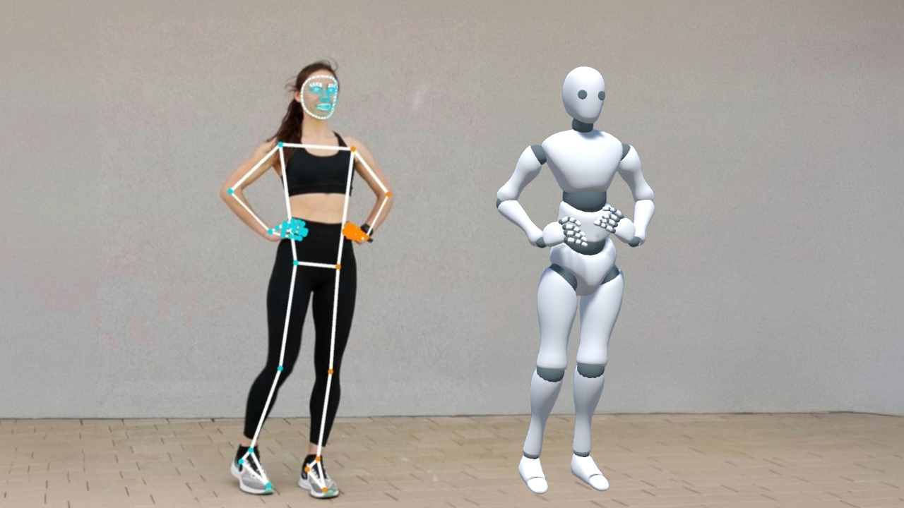
Pose estimation tools such as MediaPipe can extract human body keypoints from an image or camera feed, but a 3D avatar needs bone rotations rather than raw keypoint coordinates. This post shows how to make that conversion in Unity and how it fits into a lightweight motion capture pipeline.
Two Categories of Pose Estimation
Keypoint-Based Methods
These methods output 2D or 3D coordinates for body keypoints, typically 17 to 33 points. Common examples include the following.
- OpenPose, a classic open-source solution from CMU that supports multi-person pose estimation and outputs 25 body keypoints
- MediaPipe Pose, Google's open-source solution with 33 full-body keypoints and real-time performance on mobile devices
- VideoPose3D, which recovers 3D coordinates from 2D keypoint sequences and uses temporal information to improve depth estimation
Keypoint-based methods output coordinates. To drive a skeleton, we still need to convert those coordinates into rotations. That is the core problem this post addresses.
Parametric Human Model Methods
These methods output parameters of a parametric human body model directly, including per-joint rotations and body shape parameters. SMPL is one widely used example of such a model, but the general idea is not limited to SMPL. Common examples include the following.
- 4DHumans, which regresses SMPL parameters from a single frame. It is fast and suitable for real-time use, but lacks frame-to-frame continuity, so the motion may jitter
- WHAM, which uses temporal information from video to output a coherent SMPL sequence. Its motion is smoother than single-frame methods, and it also estimates global translation in world coordinates
- GVHMR, which further improves global trajectory accuracy on top of WHAM, especially in scenes with fast motion and large translations
Parametric human model methods already output joint rotations, so their results can often be mapped to a skeleton without the extra keypoint-to-rotation conversion step. SMPL is one common model family in this area. It is also worth noting that Meshcapade, the company behind SMPL, was recently acquired by Epic Games, so SMPL-related technology may become more deeply integrated into Unreal Engine in the future.
Comparison
| Keypoint-Based | Parametric Model-Based | |
|---|---|---|
| Output | Keypoint coordinates | Joint rotations + body shape |
| Driving a skeleton | Requires computing rotations | Direct mapping |
| Real time | Lightweight, suitable for on-device real-time use | Heavier, usually needs a GPU |
| Body contact | Only keypoint positions, making body-part contact difficult to infer | Includes body shape parameters, which helps with grounding, seated poses, and other contact-heavy cases |
| Flexibility | Not tied to a specific body model | Depends on the specific model family |
| Commercial license | Some open-source methods support free commercial use | Licensing depends on the specific model. SMPL itself requires a commercial license from Meshcapade |
From Keypoints to Bone Rotations
Now let's focus on deriving a usable bone rotation for each part of the skeleton from the available keypoints.
This conversion works because skeletal animation is defined by rotations. People of different heights performing the same motion will have different joint positions in space, but the relative rotations between bones remain consistent. As long as each bone rotation is correct, the final motion will look consistent across different body proportions.
A natural idea is to fit these keypoints with IK, but this approach has practical limitations. MediaPipe's 3D keypoints are normalized, so their values are not tied to real physical lengths. As a result, distances between keypoints are not reliable enough to serve as strong IK constraints.
At the same time, MediaPipe's 3D keypoints already describe the motion well. A more direct approach is to extract directions from those keypoints and use them to compute bone rotations.
This post assumes familiarity with Unity's Humanoid skeleton and the basics of vector cross products. The example uses MediaPipeUnityPlugin.
https://github.com/homuler/MediaPipeUnityPlugin
The complete sample code is linked near the end of the post.
Torso
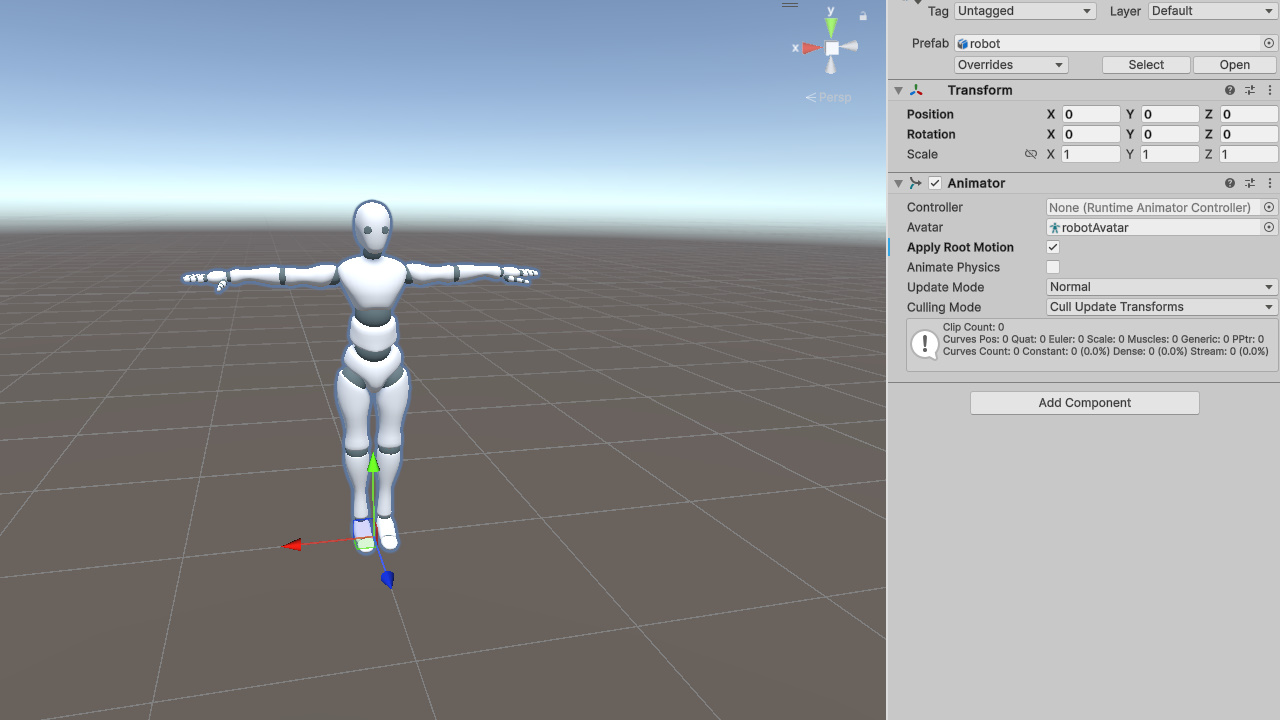
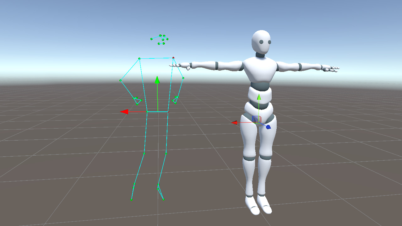
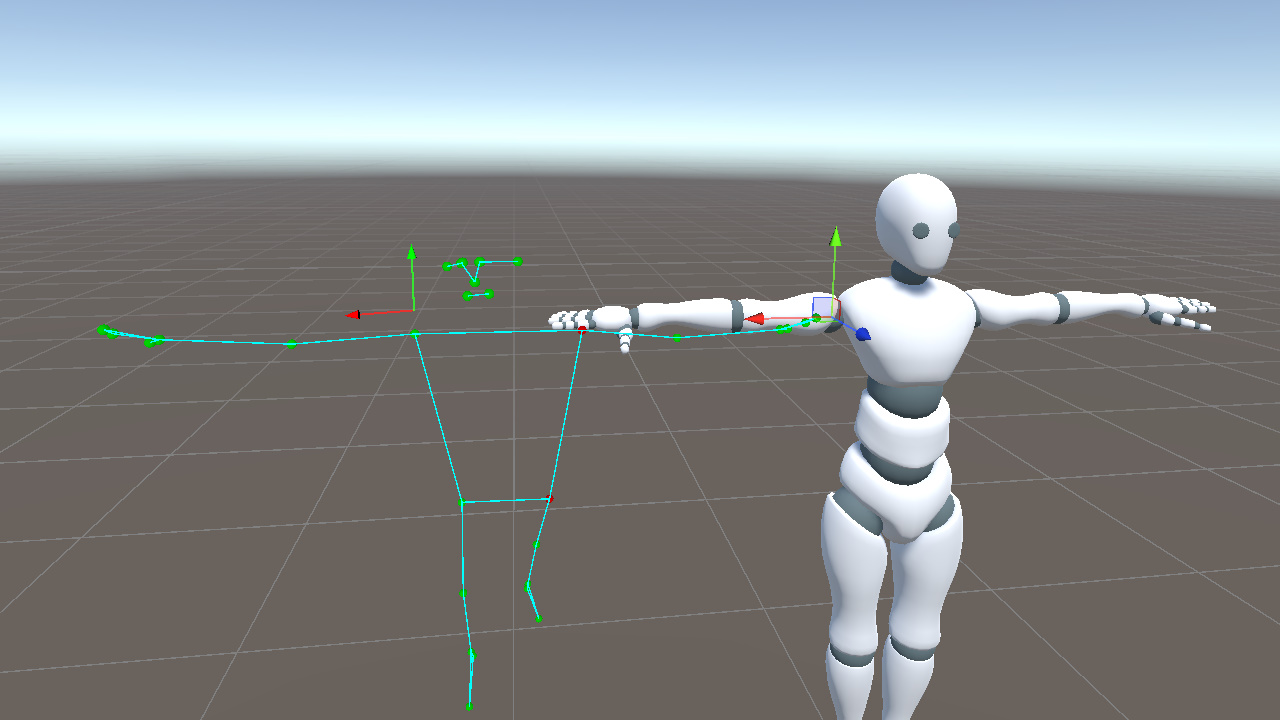
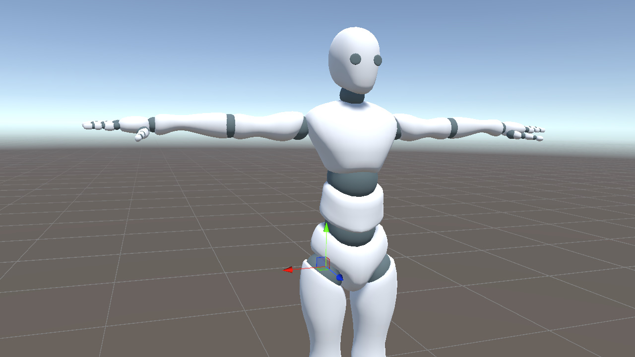
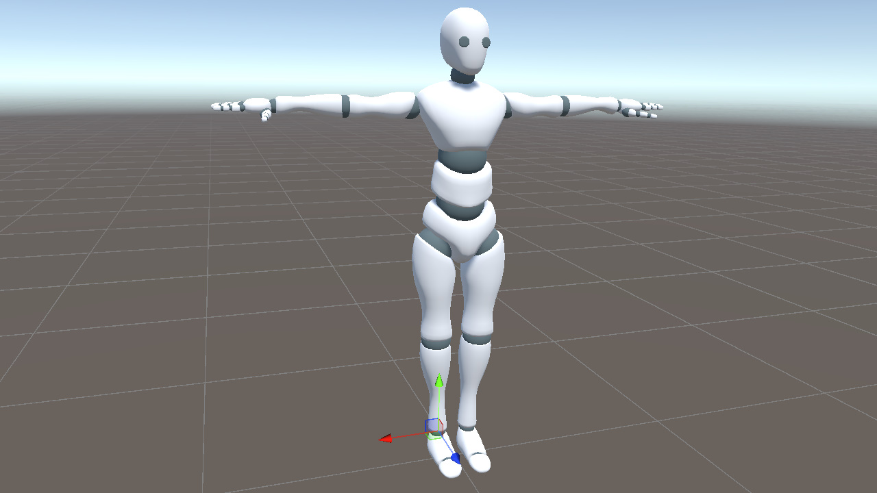
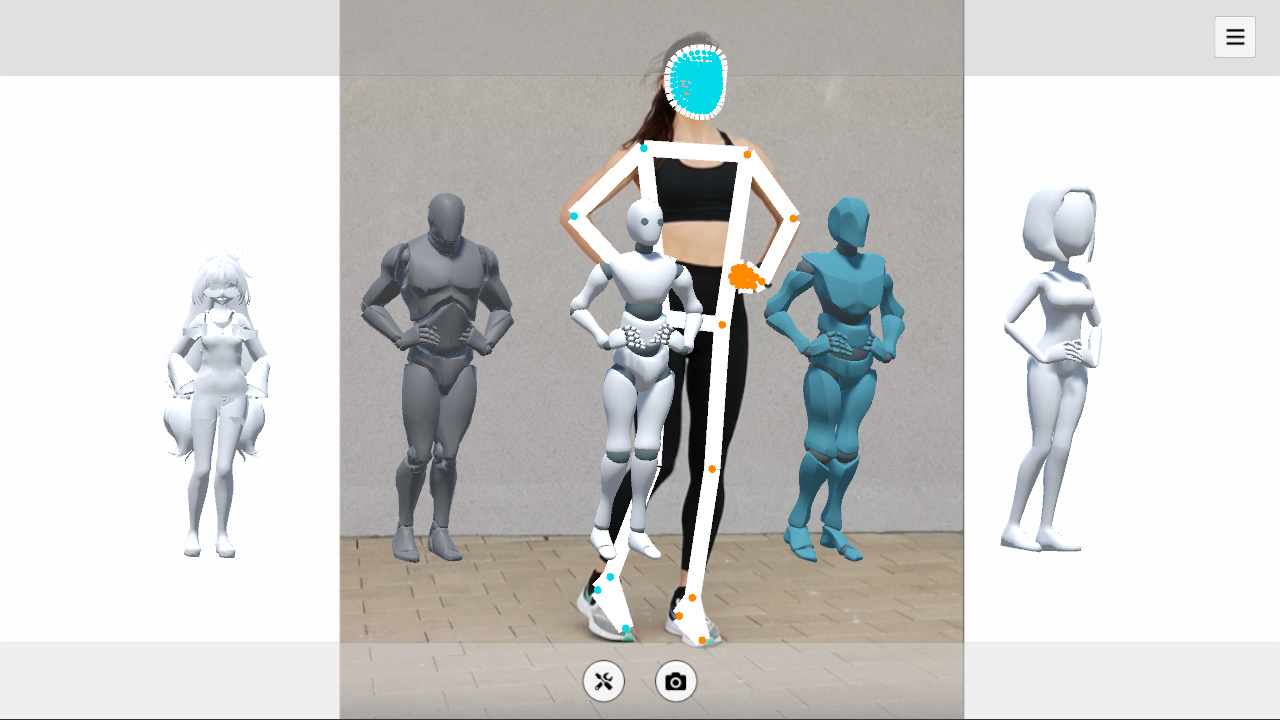
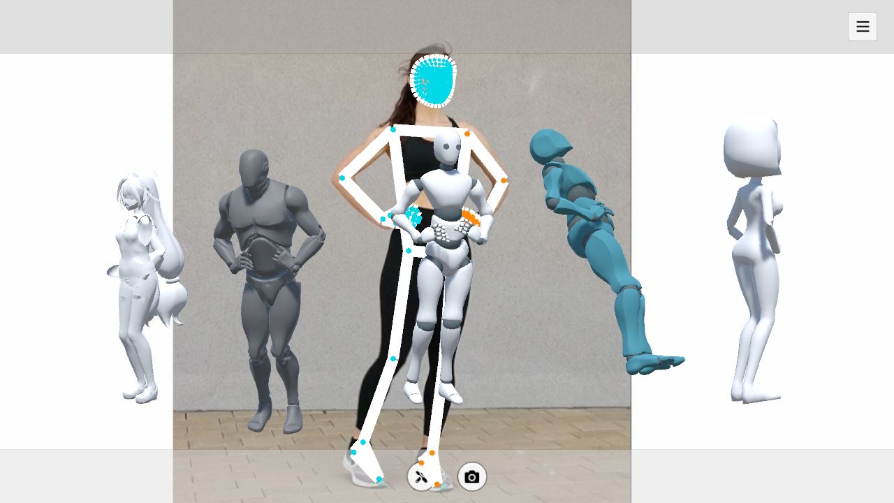
To compare keypoints and model bones in the same coordinate system, we first place the model at the Unity world origin and keep its rotation at identity. We also use Unity's positive X axis as the character's right side.
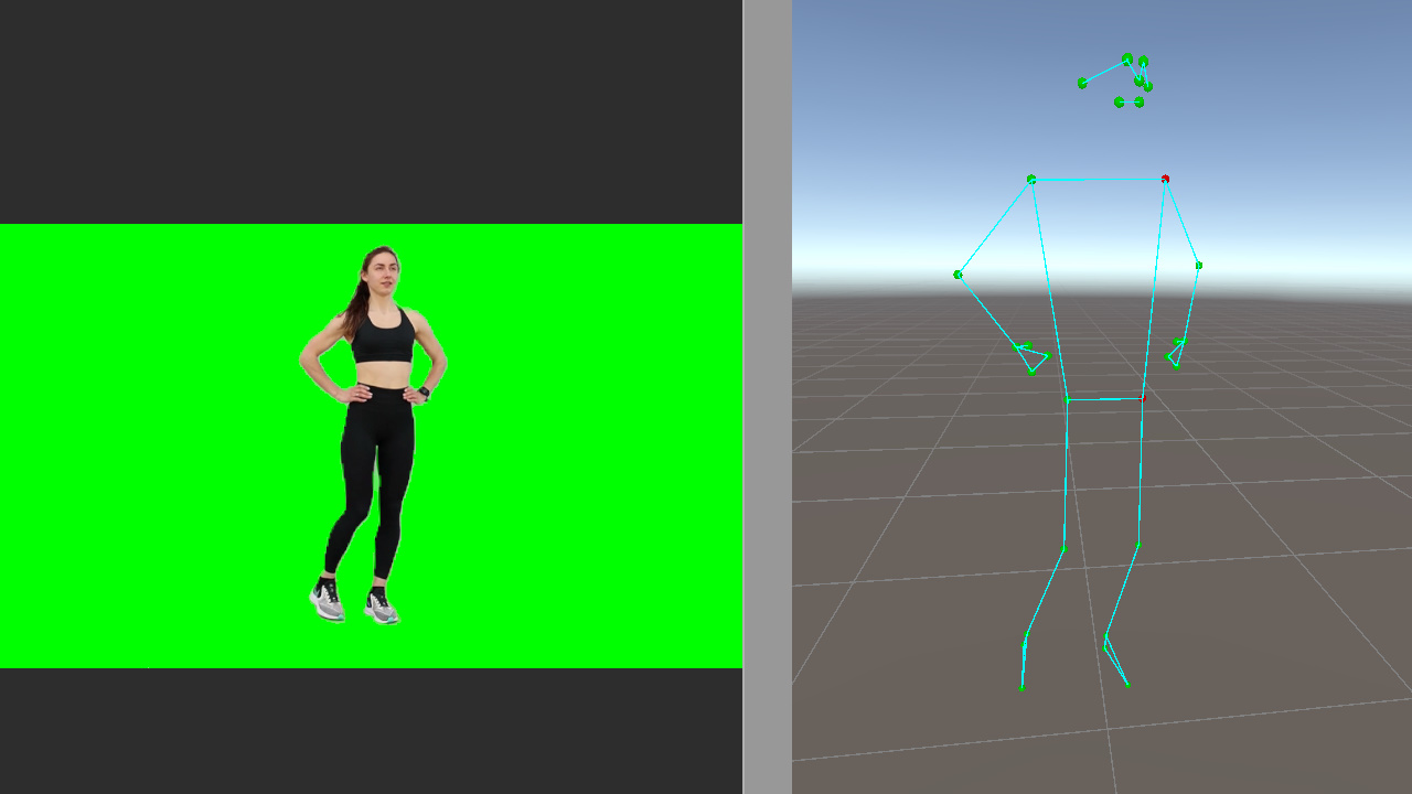
Display the pose landmarks in the scene, and mark the left shoulder and left hip in red so the left and right sides are easy to identify.
The full pose landmark index map is shown below for reference.
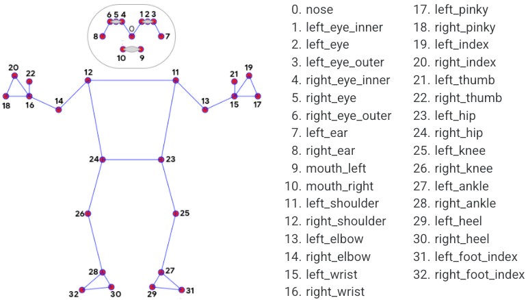
https://github.com/google-ai-edge/mediapipe/blob/master/docs/solutions/pose.md
The Hips orientation can be determined from four keypoints. Its X axis follows the direction from the left hip to the right hip, while its Y axis follows the direction from the hip center to the shoulder center.
In code, we represent these as hipXDir and hipYDir.
Vector3 hipXDir = (landmark[24] - landmark[23]).normalized;
Vector3 hipCenter = (landmark[23] + landmark[24]) * 0.5f;
Vector3 shoulderCenter = (landmark[11] + landmark[12]) * 0.5f;
Vector3 hipYDir = (shoulderCenter - hipCenter).normalized;C#
Next we need to convert these two directions into a bone rotation. Unity's Quaternion.LookRotation(forward, up) builds a rotation where the Z axis aligns with forward and the Y axis aligns as closely as possible with up.
Since we already have the X and Y directions, we can derive the Z axis with a cross product and pass it to LookRotation.
Vector3 hipZDir = Vector3.Cross(hipXDir, hipYDir).normalized;
_hips.rotation = Quaternion.LookRotation(hipZDir, hipYDir);C#
Note that LookRotation aligns the Z axis, or forward direction, exactly. Although we started from X and Y, the hipZDir constructed with the cross product forms an orthonormal basis together with hipXDir and hipYDir.
The result is that the Hips Z axis points out of the torso plane, the Y axis runs from the hip center to the shoulder center, and the X axis is determined by the other two axes. Together, they uniquely define the bone orientation.
The Hips rotation can be broken down into four steps.
- Express the keypoints in Unity space, with up/down, left/right, and forward/back directions matching Unity world coordinates
- For the Hips bone, use the plane formed by shoulders and hips to describe its orientation
- Extract the Z axis (forward) and Y axis (up) directions from these keypoints
- Pass forward and up to
LookRotationto obtain the Hips rotation
This pattern will repeat throughout the skeleton. Each bone differs mainly in which keypoints it uses and how the reference directions are constructed.
Chest is the next example. Like Hips, its orientation comes from the spatial relationship between the shoulders and hips, but the reference points are slightly different. Hips uses both hips plus the shoulder center, while Chest uses both shoulders plus the hip center. Both share the same Y axis, from hip center to shoulder center, while Chest's X axis runs from the left shoulder to the right shoulder.
Vector3 chestXDir = (landmark[12] - landmark[11]).normalized;
Vector3 chestYDir = (shoulderCenter - hipCenter).normalized;  // Shares the same Y as Hips
Vector3 chestZDir = Vector3.Cross(chestXDir, chestYDir).normalized;

_chest.rotation = Quaternion.LookRotation(chestZDir, chestYDir);C#
Limbs
MediaPipe's limb keypoints provide only two points for each segment. That is enough to determine the bone's extension direction, but LookRotation needs two directions to uniquely determine a rotation. With only one direction, the bone can still rotate freely around that axis, so the pose is not fully determined.
To resolve this, we introduce an auxiliary reference direction and use cross products to construct the remaining axes.
Right Arm
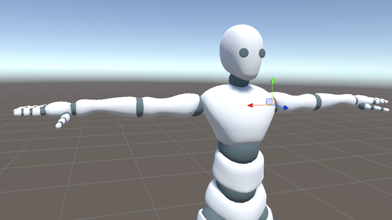
In this model, the right UpperArm bone extends along its local positive X axis.
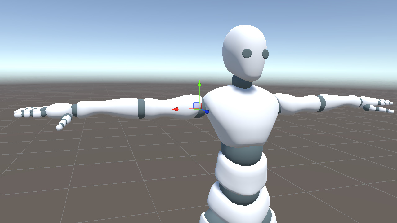
In the keypoints, the upper arm extension direction runs from point 12 (shoulder) to point 14 (elbow), so we use that vector as rUpperArmXDir. Then we use world up as the auxiliary direction and apply two cross products to construct a complete rotation.
Vector3 rUpperArmXDir = (landmark[14] - landmark[12]).normalized; // shoulder to elbow
Vector3 rUpperArmZDir = Vector3.Cross(rUpperArmXDir, Vector3.up).normalized;
Vector3 rUpperArmYDir = Vector3.Cross(rUpperArmZDir, rUpperArmXDir).normalized;
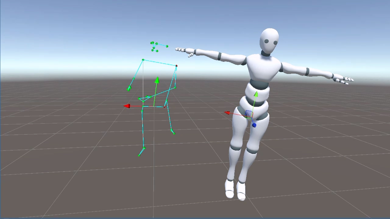
_rightUpperArm.rotation = Quaternion.LookRotation(rUpperArmZDir, rUpperArmYDir);C#However, when rUpperArmXDir is nearly parallel to Vector3.up, the cross product degenerates toward a zero vector. This usually happens when the arm is raised overhead or hanging down.
To avoid this degeneracy, we replace the auxiliary direction when the arm approaches a vertical direction. From the model, we can observe the following.
When the arm is raised (rUpperArmXDir ≈ Vector3.up), the bone's Y axis points toward world -X (the body's left side).
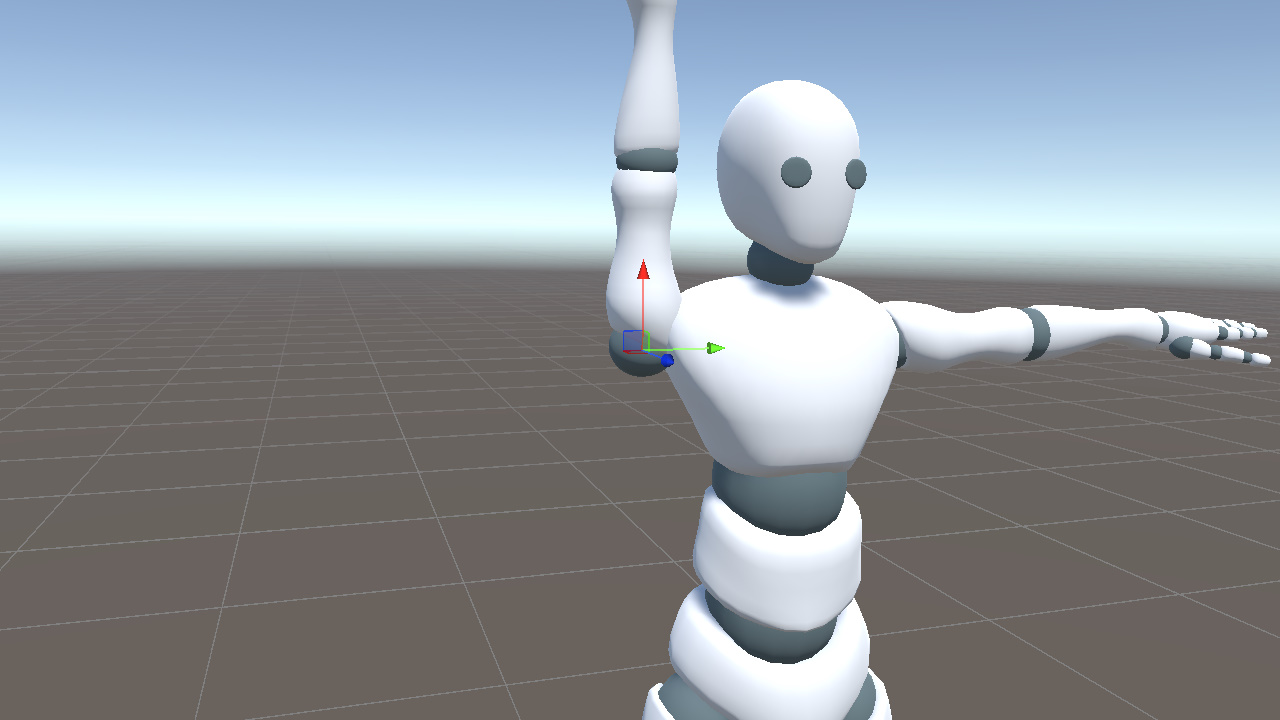
When the arm is lowered (rUpperArmXDir ≈ -Vector3.up), the bone's Y axis points toward world +X (the body's right side).
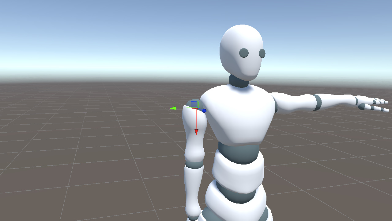
We can therefore use the dot product to check whether the current direction is almost parallel to Vector3.up. If it is, we switch the auxiliary direction to -Vector3.right or +Vector3.right based on the arm's orientation, avoiding the degenerate cross product.
Vector3 aux = Mathf.Abs(Vector3.Dot(rUpperArmXDir, Vector3.up)) < 0.99f
    ? Vector3.up : (rUpperArmXDir.y > 0 ? -Vector3.right : Vector3.right);
Vector3 rUpperArmZDir = Vector3.Cross(rUpperArmXDir, aux).normalized;
Vector3 rUpperArmYDir = Vector3.Cross(rUpperArmZDir, rUpperArmXDir).normalized;C#
The right lower arm uses elbow (14) to wrist (16) as its direction. The logic is identical. Only the keypoints change.
Vector3 rLowerArmXDir = (landmark[16] - landmark[14]).normalized;  // elbow to wrist
Vector3 aux = Mathf.Abs(Vector3.Dot(rLowerArmXDir, Vector3.up)) < 0.99f
    ? Vector3.up : (rLowerArmXDir.y > 0 ? -Vector3.right : Vector3.right);
Vector3 rLowerArmZDir = Vector3.Cross(rLowerArmXDir, aux).normalized;
Vector3 rLowerArmYDir = Vector3.Cross(rLowerArmZDir, rLowerArmXDir).normalized;
_rightLowerArm.rotation = Quaternion.LookRotation(rLowerArmZDir, rLowerArmYDir);C#
Left Arm
The left upper arm is mirrored. Its positive X axis points left, opposite to the shoulder-to-elbow extension direction. When constructing xDir, we therefore reverse the vector and go from elbow to shoulder.
// Left upper arm elbow(13) to shoulder(11)
Vector3 lUpperArmXDir = (landmark[11] - landmark[13]).normalized;

// Left lower arm wrist(15) to elbow(13)
Vector3 lLowerArmXDir = (landmark[13] - landmark[15]).normalized;C#
The reference direction still uses world up. Near vertical poses use the same degeneracy handling as the right arm.
- When the left arm is raised, lUpperArmXDir ≈ -Vector3.up, and the bone Y axis points toward world +X (the body's right side)
- When the left arm is lowered, lUpperArmXDir ≈ +Vector3.up, and the bone Y axis points toward world -X (the body's left side)
lUpperArmXDir.y > 0 ? -Vector3.right : Vector3.right covers both cases automatically. The following aux, zDir, yDir, and LookRotation calculations are identical to the right arm.
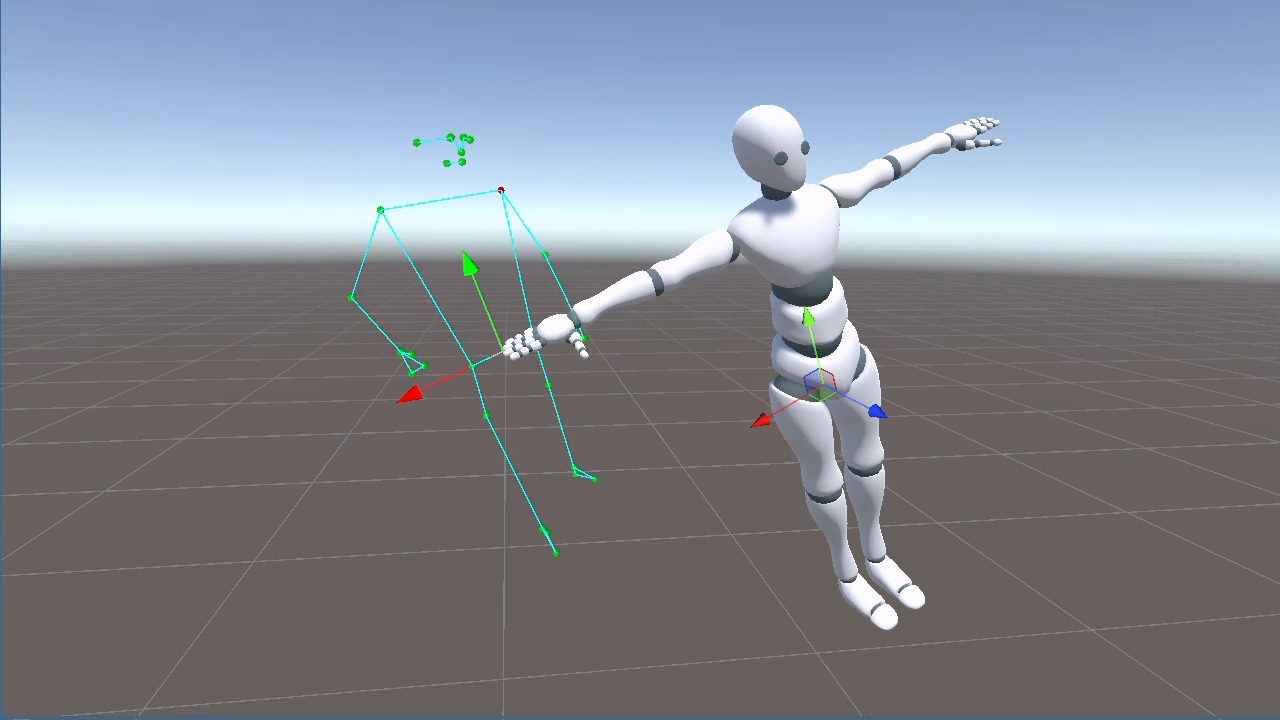
Right Leg
Legs use a different axis convention from arms. The right thigh bone extends along the local negative Y axis, from hip to knee, while its local X axis points to the body's right side.
From this, we extract two directions from the keypoints.
- landmark 23 to 24 (left hip to right hip), as the X direction
- landmark 26 to 24 (knee to hip), as the Y direction
Vector3 legXDir = (landmark[24] - landmark[23]).normalized;  // left hip to right hip (shared between legs)
Vector3 rLegYDir = (landmark[24] - landmark[26]).normalized;  // knee to hip
Vector3 rLegZDir = Vector3.Cross(legXDir, rLegYDir).normalized;
_rightUpperLeg.rotation = Quaternion.LookRotation(rLegZDir, rLegYDir);C#
We do not handle degeneracy here the same way we did for the arms, because legXDir (left/right) and rLegYDir (up/down) are naturally close to orthogonal. They only become nearly parallel when the leg points completely sideways, which is rare in practical capture data.
The right shin is handled the same way. Knee (26) to ankle (28) determines the extension direction, and legXDir is reused as the X axis.
Vector3 rShinYDir = (landmark[26] - landmark[28]).normalized;  // ankle to knee
Vector3 rShinZDir = Vector3.Cross(legXDir, rShinYDir).normalized;
_rightLowerLeg.rotation = Quaternion.LookRotation(rShinZDir, rShinYDir);C#
The right foot is different. Its bone extends along the local positive Z axis, from ankle to toe, rather than along the local Y axis like the thigh and shin.
Therefore zDir comes directly from the keypoints. Combined with legXDir, it lets us derive yDir with a cross product.
Vector3 rFootZDir = (landmark[32] - landmark[28]).normalized;  // ankle to toe
Vector3 rFootYDir = Vector3.Cross(rFootZDir, legXDir).normalized;
_rightFoot.rotation = Quaternion.LookRotation(rFootZDir, rFootYDir);C#
Left Leg
The left leg is symmetric to the right leg. It reuses the same legXDir. Only the keypoint indices change from 24/26/28/32 to 23/25/27/31.
- Left upper leg, hip(23) to knee(25), Y positive = knee to hip =
landmark[23] - landmark[25] - Left shin, knee(25) to ankle(27), Y positive = ankle to knee =
landmark[25] - landmark[27] - Left foot, ankle(27) to toe(31), Z positive =
landmark[31] - landmark[27]
// Left upper leg
Vector3 lLegYDir = (landmark[23] - landmark[25]).normalized;
Vector3 lLegZDir = Vector3.Cross(legXDir, lLegYDir).normalized;
_leftUpperLeg.rotation = Quaternion.LookRotation(lLegZDir, lLegYDir);

// Left shin
Vector3 lShinYDir = (landmark[25] - landmark[27]).normalized;
Vector3 lShinZDir = Vector3.Cross(legXDir, lShinYDir).normalized;
_leftLowerLeg.rotation = Quaternion.LookRotation(lShinZDir, lShinYDir);

// Left foot
Vector3 lFootZDir = (landmark[31] - landmark[27]).normalized;
Vector3 lFootYDir = Vector3.Cross(lFootZDir, legXDir).normalized;
_leftFoot.rotation = Quaternion.LookRotation(lFootZDir, lFootYDir);C#
Head
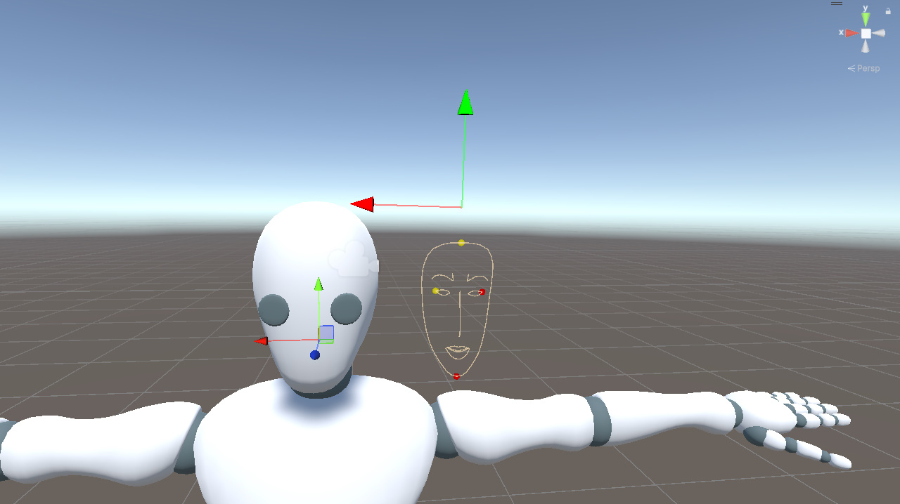
Next, we also display the face landmarks in Unity space. As with the pose landmarks, selected points are marked red to make the vertical and horizontal relationships easier to read.
From the visualization, we can see that face landmarks follow head rotation more closely than pose landmarks. For that reason, we use face landmarks to drive the head rotation.
In the model, the head bone's local X axis points to the character's right side, and its local Y axis points upward. Similar to Hips, we pick four face landmarks to construct a local coordinate system.
- Forehead (10, the yellow point near the top of the face) and chin (152, the red point at the bottom) determine the vertical direction
- Right eye outer corner (33, the yellow point on the right side of the face) and left eye outer corner (263, the red point on the left) determine the horizontal direction
From these points, we extract two directions.
- headYDir, chin pointing to forehead
- headXDir, left eye outer corner pointing to right eye outer corner
Then we derive the third axis with a cross product and pass the result to LookRotation.
Vector3 headYDir = (faceLandmarks[10] - faceLandmarks[152]).normalized;
Vector3 headXDir = (faceLandmarks[33] - faceLandmarks[263]).normalized;
Vector3 headZDir = Vector3.Cross(headXDir, headYDir).normalized;

_head.rotation = Quaternion.LookRotation(headZDir, headYDir);C#
This gives the full head orientation.
In practice, part of this rotation can also be distributed to the neck bone for a more natural transition. That refinement is outside the scope of this post.
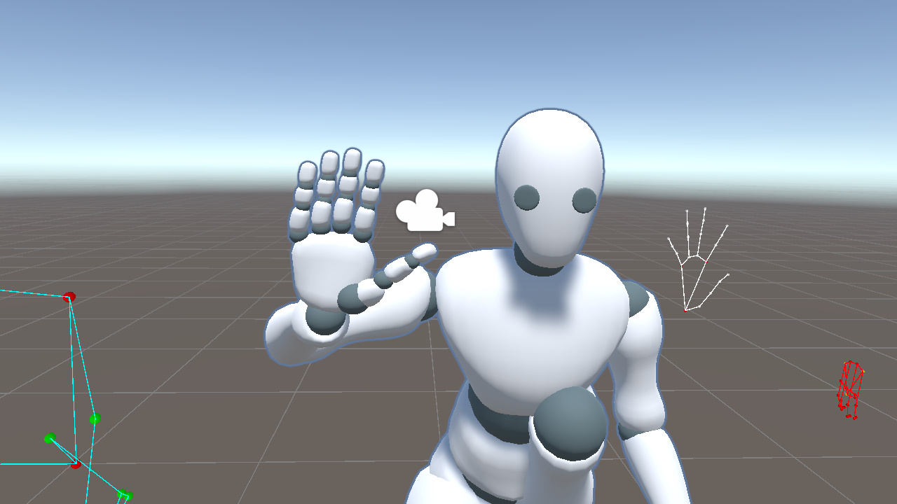
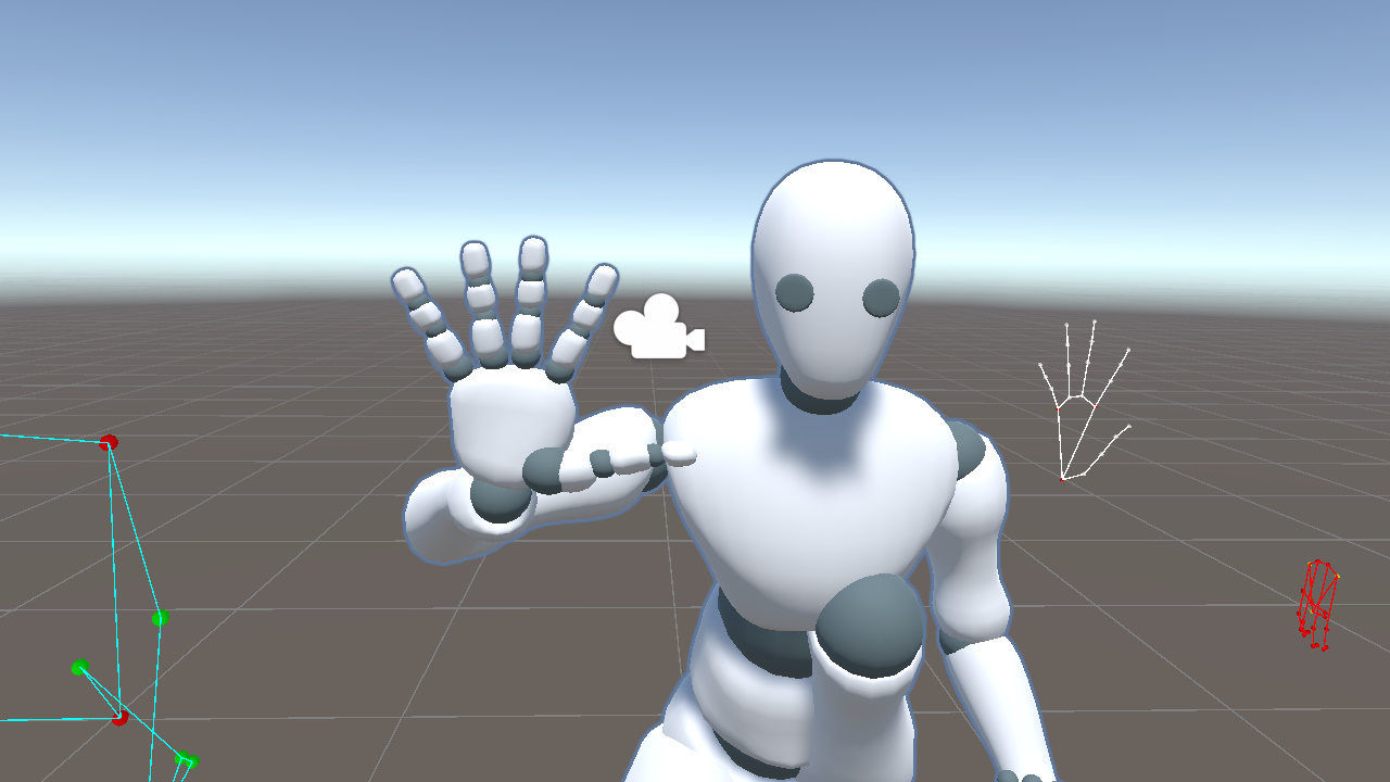
Hands
Next, we move on to the hands and fingers. We first display the hand landmarks in Unity space, with the left hand marked red for clarity.
As the video shows, hand landmarks track palm orientation more accurately than pose landmarks and provide full finger joint information. For that reason, we use hand landmarks to drive the hand pose.
The hand landmark index map is shown below for reference.
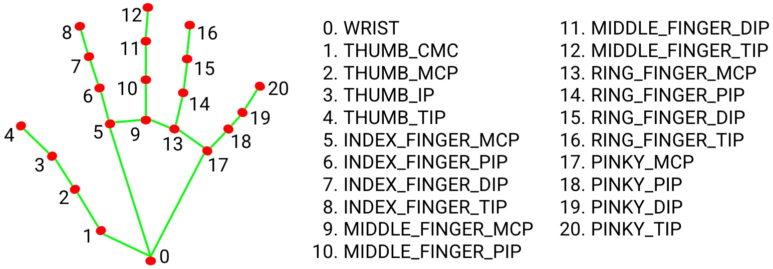
https://github.com/google-ai-edge/mediapipe/blob/master/docs/solutions/hands.md
Right Palm
In this model, the right palm follows the same convention as the arm and extends along the local positive X axis.
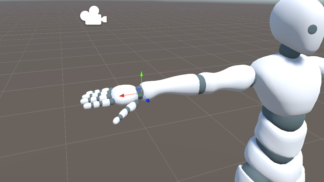
The wrist (0), index base (5), and pinky base (17) form a triangle that covers most of the palm plane.
Based on these three points, we construct two directions.
- toIndex, wrist to index base
- toPinky, wrist to pinky base
Next, taking the cross product of toIndex and toPinky gives handYDir, which points out of the palm plane toward the back of the hand.
We also use the direction from the wrist to the middle finger base (0 to 9) as the palm's extension direction.
Vector3 rToIndex = (handLandmarks[5] - handLandmarks[0]).normalized;
Vector3 rToPinky = (handLandmarks[17] - handLandmarks[0]).normalized;
Vector3 rHandYDir = Vector3.Cross(rToIndex, rToPinky).normalized;
Vector3 rHandXDir = (handLandmarks[9] - handLandmarks[0]).normalized;  // wrist to middle finger baseC#
Then we derive the third axis with the cross product of rHandXDir and rHandYDir, and use the result to build the rotation.
Vector3 rHandZDir = Vector3.Cross(rHandXDir, rHandYDir).normalized;
_rightHand.rotation = Quaternion.LookRotation(rHandZDir, rHandYDir);C#
This defines the palm orientation.
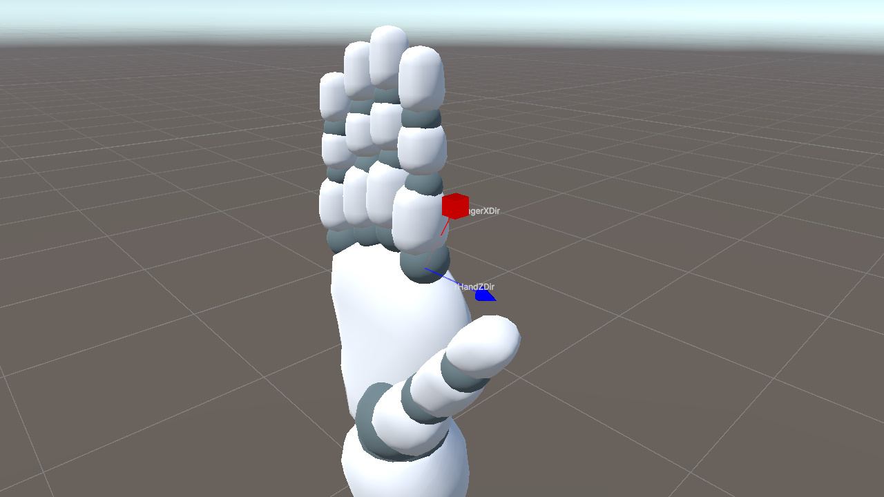
Right Four Fingers
The four fingers, excluding the thumb, use the same convention as the palm. Their bones extend along the local X axis. Each bone segment can be determined by two adjacent keypoints.
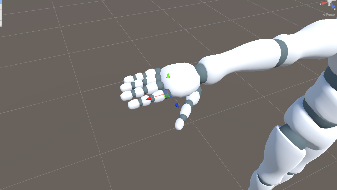
rFingerXDir determines the finger's extension direction, but LookRotation still needs two directions to define the rotation fully.
A natural idea is to reuse the palm's coordinate system.
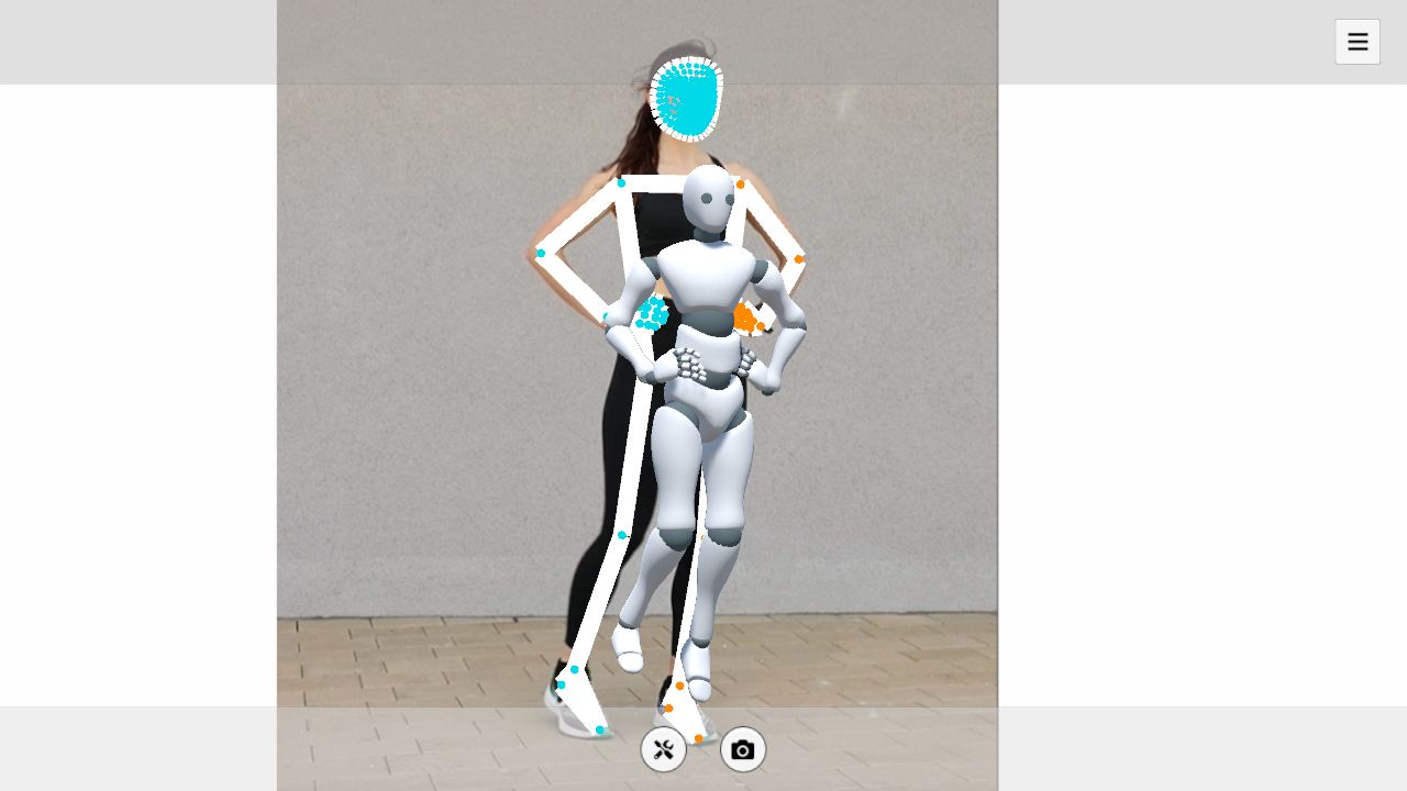
One option is to use the palm's Y axis, the direction from the palm toward the back of the hand. This breaks down when the fingers bend significantly. Their local orientation gradually leaves the palm plane, so their Y direction may no longer match the palm's Y direction and may even flip, causing unstable poses.
Another option is to use the palm's Z axis and treat rHandZDir as each finger's Z direction. This direction stays relatively stable during hand motion, but it also locks all fingers to the same forward direction. As a result, the model cannot represent the spread angle between fingers. In the figure below, the keypoints show the fingers spread out, but the model keeps them closed.
Instead, each finger needs its own Z axis direction.
The key is the cross product. Given two input directions, it gives us a third direction that is orthogonal to both.
We already have two useful directions.
- rHandZDir from the palm
- rFingerXDir, the finger extension direction
First, we take the cross product of rHandZDir and rFingerXDir to get rFingerYDir.
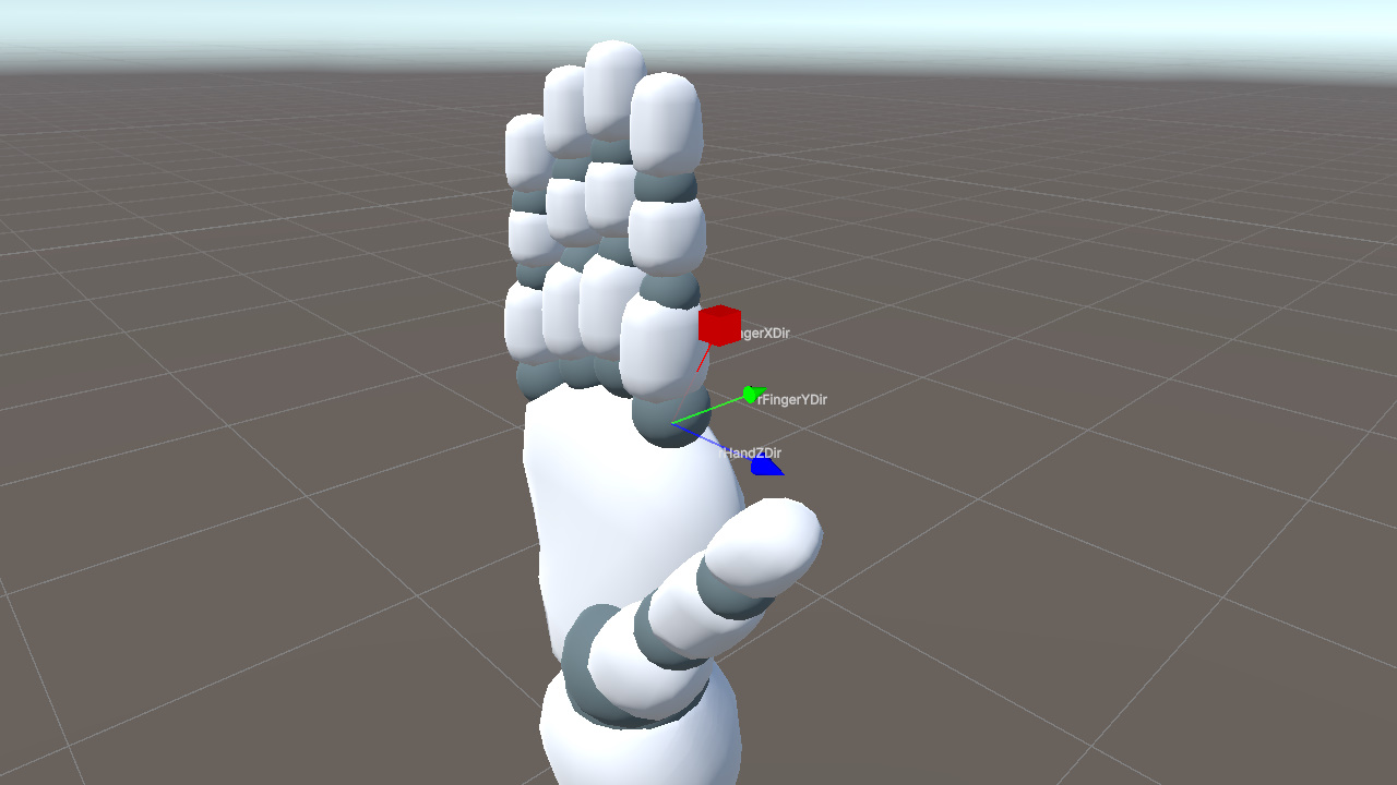
Then, we take the cross product of rFingerXDir and rFingerYDir to get rFingerZDir, completing the finger's local coordinate system.

Passing rFingerZDir and rFingerYDir to LookRotation makes the bone's X axis align exactly with rFingerXDir.
This gives each finger a Z direction based on the palm, while still allowing it to change with the finger's spread angle.
The following code uses the index finger base joint (5 to 6) as an example.
Vector3 rFingerXDir = (handLandmarks[6] - handLandmarks[5]).normalized;
Vector3 rFingerYDir = Vector3.Cross(rHandZDir, rFingerXDir).normalized;
Vector3 rFingerZDir = Vector3.Cross(rFingerXDir, rFingerYDir).normalized;
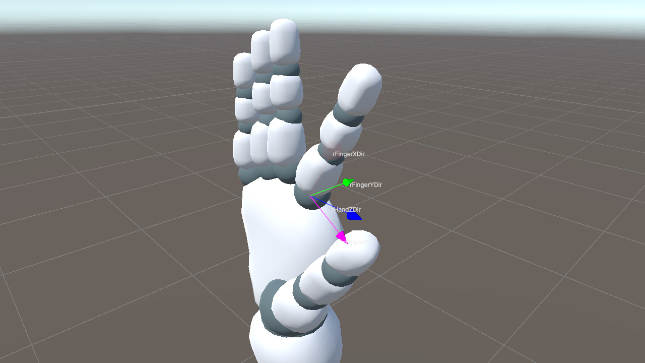
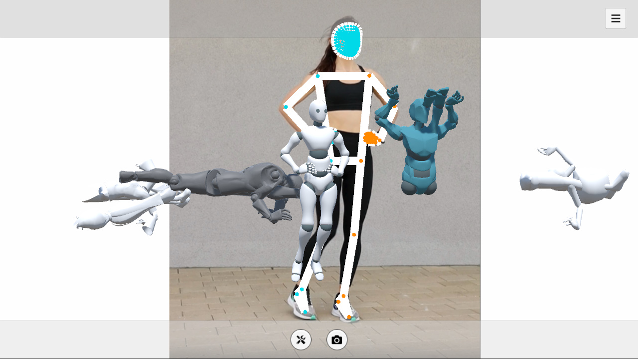
fingerBone.rotation = Quaternion.LookRotation(rFingerZDir, rFingerYDir);C#As shown below, computing a separate Z axis for each finger correctly preserves the finger spread.
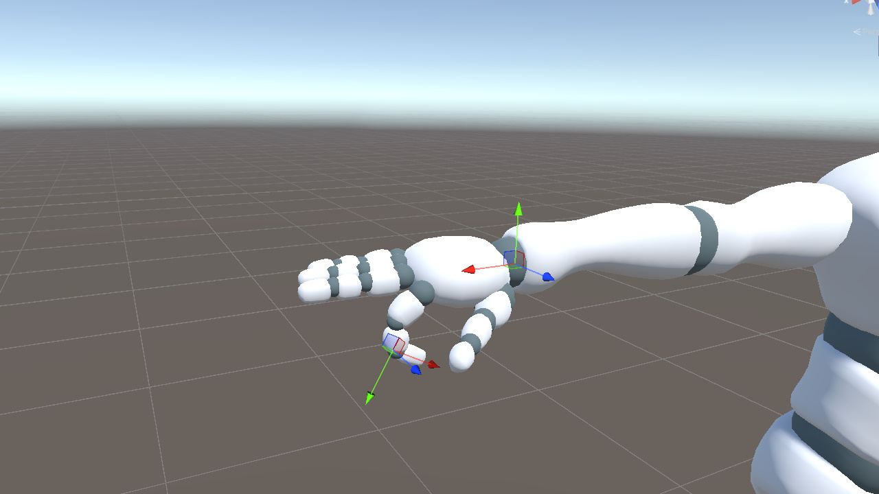
Right Thumb
The thumb requires separate handling.
The thumb bone's local axes are not aligned with the actual extension direction of the mesh. In other words, no local axis can be used directly as the "bone extension direction". If we reuse the four-finger approach directly, the result will be incorrect.
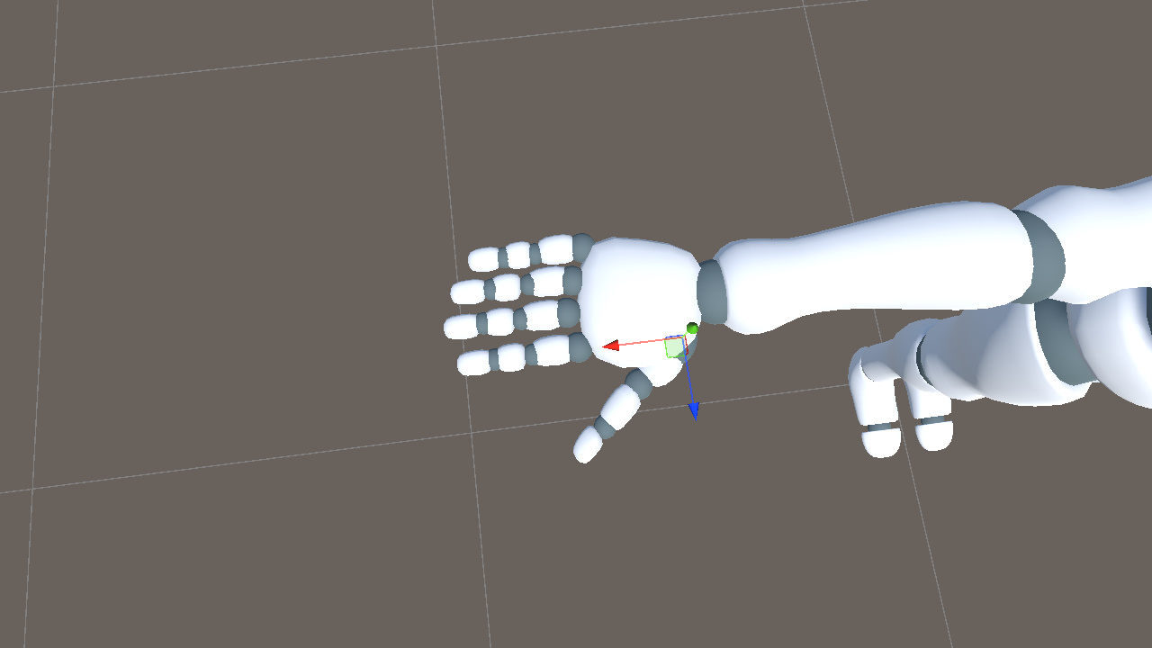
In the reference pose, rotating the thumb bone around the world Y axis by roughly -40 degrees aligns its local +X axis with the thumb mesh's actual extension direction. After this alignment, we can treat the thumb's local +X axis as its extension direction, just like the other fingers.
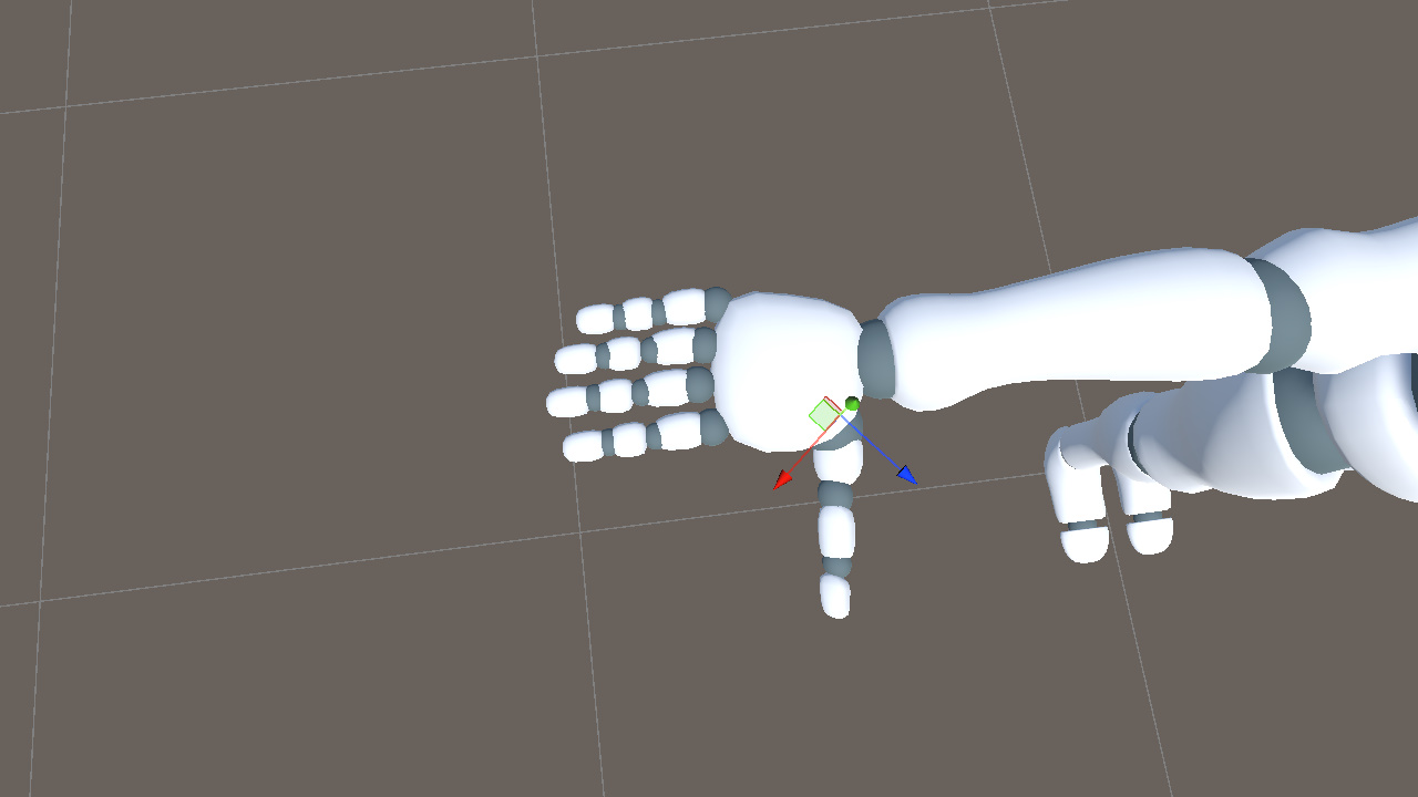
At runtime, we first construct the thumb's local coordinate system from the keypoints in the same way as the other fingers. This gives the rotation for the aligned thumb axis. We then apply the opposite rotation, +40 degrees around Y, to convert that result back to the actual model's thumb orientation.
// Shared across the three thumb segments (idx = 1, 2, 3 for proximal, intermediate, distal)
Vector3 rThumbXDir = (handLandmarks[idx + 1] - handLandmarks[idx]).normalized;
Vector3 rThumbYDir = Vector3.Cross(rHandZDir, rThumbXDir).normalized;
Vector3 rThumbZDir = Vector3.Cross(rThumbXDir, rThumbYDir).normalized;
thumbBone.rotation = Quaternion.LookRotation(rThumbZDir, rThumbYDir) * Quaternion.Euler(0f, 40f, 0f);C#
Here, the +40 degree value is a fixed compensation chosen for this model. Later, we will derive a more general way to compute this kind of compensation.
Left Hand
The left hand mirrors the right hand, so lHandXDir and each lFingerXDir need to be negated. The cross product order for lHandYDir must also be reversed, from Cross(rToIndex, rToPinky) to Cross(lToPinky, lToIndex), because the index finger and pinky appear in the opposite order on the left hand.
This completes the full mapping from keypoints to bone rotations.
Summary
The same idea applies across the skeleton. For each bone, we first inspect the model to see which local axis follows the bone's extension direction. Then we choose keypoints that describe the same extension direction. Finally, we construct the remaining axes with cross products and use them to build the rotation.
This works for the example model because its bone axes mostly align with Unity's world axes, and most mesh segments follow one of the bone's local axes. The thumb is the exception because its bone axes are aligned, but the mesh does not extend along a local axis, so it needs extra compensation.
Real projects often involve models that do not satisfy these assumptions. Applying the method directly to those models can produce incorrect results.
Next, we will extend the method so it can handle arbitrary bone axes and mesh directions.
Supporting Any Model
To support different models, we need to handle two kinds of mismatch. The bone axes may not match the reference coordinate system, and the mesh may not extend along the bone's chosen local axis. We handle these with two compensation terms.
Axis Misalignment
During initialization, record each bone's world rotation as initRot. This captures the fixed transformation from the bone's local space to world space.
Quaternion initRot = bone.rotation;C#At runtime, LookRotation(zDir, yDir) produces the target rotation in world space. Multiplying it by initRot is equivalent to applying that rotation on top of the reference pose, yielding the bone's current world rotation.
bone.rotation = Quaternion.LookRotation(zDir, yDir) * initRot;C#Mesh Direction Offset
The thumb already showed this problem. In essence, the bone's local axis has a fixed offset from the mesh's actual extension direction. To handle it, construct a reference rotation, initAxisRot, during initialization so that the bone axis aligns with the mesh direction. After computing the target bone-axis orientation, cancel this reference transform to recover the correct mesh orientation.
For this compensation, we need to decide two things. First, choose which local bone axis represents the bone's extension. Then, choose the mesh direction that axis should align to.
- Bone axis is chosen based on the bone's layout. For vertically arranged bones such as Hips, Chest, legs, and head, use the Y axis. For horizontally arranged bones such as arms and fingers, use the X axis. For depth-oriented bones such as feet, use the Z axis.
- Mesh direction uses the direction from the current bone to its child when a child bone exists. If there is no child bone, assume the direction continues from the previous segment.
For the right thumb proximal joint, the X axis should follow the direction from RightThumbProximal to RightThumbIntermediate. From that reference direction, we can construct initAxisRot as follows.
// Captured once in Start()
Transform thumbProx = animator.GetBoneTransform(HumanBodyBones.RightThumbProximal);
Transform thumbInt  = animator.GetBoneTransform(HumanBodyBones.RightThumbIntermediate);

Vector3 rHandZDir_T = ...;  // palm normal at initialization, same construction as runtime rHandZDir

Vector3 rThumbXDir_T = (thumbInt.position - thumbProx.position).normalized;  // mesh direction
Vector3 rThumbYDir_T = Vector3.Cross(rHandZDir_T, rThumbXDir_T).normalized;
Vector3 rThumbZDir_T = Vector3.Cross(rThumbXDir_T, rThumbYDir_T).normalized;

Quaternion initAxisRot = Quaternion.LookRotation(rThumbZDir_T, rThumbYDir_T);C#
At runtime, we still compute the target rotation as usual, but cancel this transformation by multiplying by its inverse on the right.
// In LateUpdate, every frame
Vector3 rThumbXDir = (thumbLandmarkInt - thumbLandmarkProx).normalized;
Vector3 rThumbYDir = Vector3.Cross(rHandZDir, rThumbXDir).normalized;
Vector3 rThumbZDir = Vector3.Cross(rThumbXDir, rThumbYDir).normalized;

thumbProx.rotation =
    Quaternion.LookRotation(rThumbZDir, rThumbYDir) *
    Quaternion.Inverse(initAxisRot);C#
In this form, LookRotation gives the orientation built from the keypoints. Multiplying by Inverse(initAxisRot) converts that orientation back into the model's actual thumb space.
For the right thumb discussed earlier, this method gives an initAxisRot of approximately (-1, -38, -11), which is consistent with the earlier visual observation.
It is also worth noting that the mesh-direction compensation described here is a practical solution, but not necessarily the optimal one.
Combining
We can now combine the two compensation terms. LookRotation(zDir, yDir) builds the rotation from the keypoints, initAxisRot corrects the mesh-direction offset, and initRot restores the bone's original axis alignment.
bone.rotation =
    Quaternion.LookRotation(zDir, yDir) *
    Quaternion.Inverse(initAxisRot) * initRot;C#
In this formula, each term has a fixed role.
- initAxisRot compensates for the mesh extension direction not matching the chosen local bone axis
- initRot compensates for the bone's initial axes not matching the reference coordinate system
The compensation part is constant after initialization, so we can precompute it once for each bone.
Quaternion compensation = Quaternion.Inverse(initAxisRot) * initRot;  // precompute

bone.rotation = Quaternion.LookRotation(zDir, yDir) * compensation;  // every frameC#
With this cached compensation, the same rotation-solving logic can be applied across different models and bones.
Because initAxisRot and initRot are captured from the same initial pose, pose-dependent terms change together and cancel out. What remains is the bone's own geometric offset, so the model does not need to be in a strict T-pose during initialization.
Handling Initial Rotation
At the beginning of the article, we placed the model at the Unity world origin and kept its rotation at identity. The derivation so far follows that assumption. In real projects, however, characters are often placed in the scene with a specific facing direction. If we use the formula above directly, the driven pose remains in world coordinates and can deviate from the character's intended facing direction.
To handle this, record the character's initial world rotation during initialization.
Quaternion rootInit = transform.rotation; // captured once in StartC#At runtime, apply rootInit as a prefix to the computed bone rotation.
bone.rotation = rootInit * Quaternion.LookRotation(zDir, yDir) * compensation;C#Here, Quaternion.LookRotation(zDir, yDir) * compensation is the target pose computed in world coordinates. Multiplying by rootInit maps that pose into the coordinate system defined by the character's initial facing direction, keeping the driven result aligned with the character.
At this point, we have a complete keypoint-to-rotation pipeline that can handle different model setups and different initial facing directions.
Limitations and Improvements
This post describes a basic approach to animating a skeleton from keypoint-derived bone rotations. It can serve as the core of a simple motion capture prototype, but several parts still need further improvement.
Hip Translation
MediaPipe's pose world landmarks use the midpoint between the two hips as the origin, so the Hips coordinate is always (0, 0, 0). This means absolute character translation cannot be obtained directly.
To recover translation, we can estimate it from other cues, for example.
- Infer vertical translation from the overall height change of all keypoints
- Estimate horizontal translation from the change in Hips image position in the 2D normalized coordinates
Data Jitter
Even with MediaPipe's smoothing enabled, the keypoints can still jitter noticeably.
Common improvements include the following.
- Smooth the keypoint positions over time before computing rotations, so less noise enters the rotation solve
- Interpolate the resulting rotations to make the output motion more continuous
Rotation Around Limb Long Axis
In the method above, arm and leg rotations use auxiliary directions such as world up or hip width. These directions are enough to aim a bone from one joint to the next, such as from shoulder to elbow, but they do not fully capture twist around the bone's own long axis.
As a result, palm or foot twist can become concentrated on the end bones, such as Hand or Foot, while nearby bones such as the lower arm or shin do not share enough of that rotation. This can make the deformation look unnatural.
Possible improvements include the following.
- Use auxiliary directions that better match local motion, like constructing a normal from the joint bend plane, to more accurately reflect the actual bone rotation
- Distribute end twist proportionally to adjacent bones for more even and natural deformation
This wraps up the main idea behind converting MediaPipe keypoints into bone rotations for a 3D avatar. The example project below shows one way to put the full process together in Unity. If you have questions or ideas, feel free to leave a comment.
Using the Example Code
Example project
https://github.com/SunnyViewTech/MoCapLite
Steps
1. Download MediaPipeUnity.0.16.3.unitypackage and import it into the project.
https://github.com/homuler/MediaPipeUnityPlugin/releases/tag/v0.16.3
2. Use HolisticTrackingSolution.cs from MoCapLite to replace the file with the same name under the following path.
\Assets\MediaPipeUnity\Samples\Scenes\Legacy\Holistic
3. Open the example scene.
\Assets\MediaPipeUnity\Samples\Scenes\Legacy\Holistic\Holistic.unity
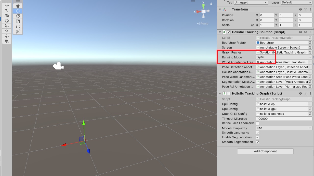
4. Set Running Mode to Sync.
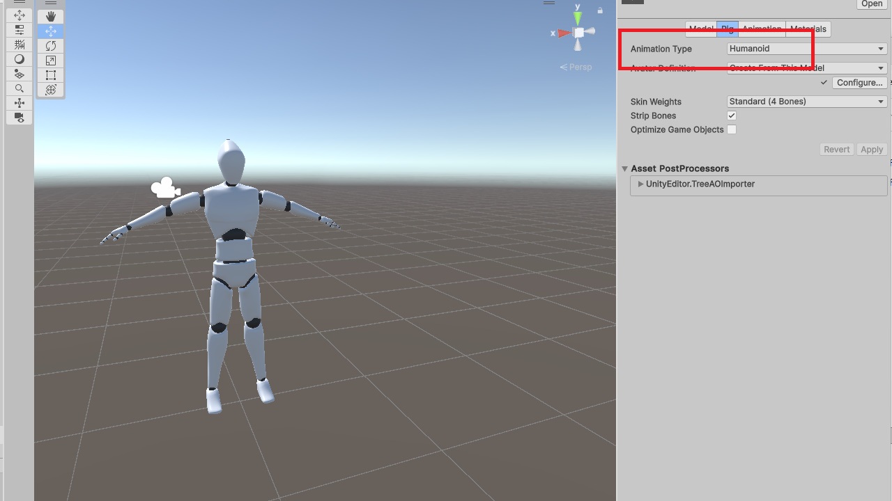
5. Import a character model and set its Rig type to Humanoid.
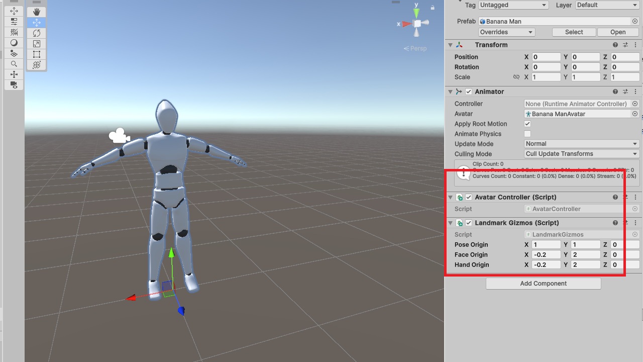
6. Add the AvatarController component to the model. You can optionally add LandmarkGizmos for debugging.
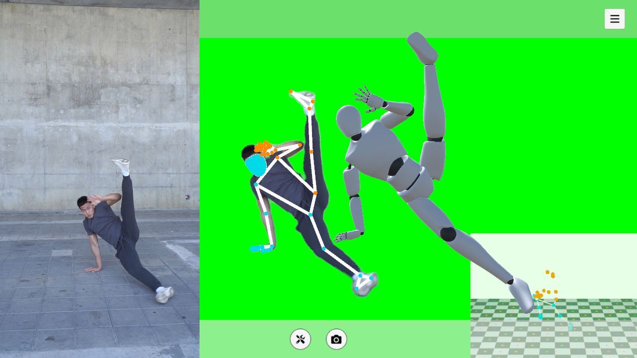
7. Run the scene to see the motion capture result.
Notes
The sample code demonstrates the basic pipeline from keypoints to bone rotations. One small difference is that the initial-rotation handling in the code is more general than the simplified version described in this post.
Resources
Some related open-source projects for reference
https://github.com/yeemachine/kalidokit
https://github.com/digital-standard/ThreeDPoseUnityBarracuda
Video resources used in this post
https://pexels.com/video/woman-in-black-activewear-doing-leg-and-hip-exercise-5510143
https://pexels.com/video/young-man-practicing-break-dance-5363330